EO Reactor Design Types: Choosing the Right Configuration
Reactor geometry sets the ceiling on current efficiency before a single volt is applied. Here is how the major architectures compare and where each one earns its place.
electrochemical oxidation eo reactor design types
EO Reactor Design Types
Decision Gate
Not sure if EO applies? Start with the decision gate before committing to a design path.

Why This Matters

The reactor is not a container you drop electrodes into afterward. Plate spacing, flow path, and electrode arrangement determine current distribution, mass transfer to the electrode surface, and ultimately how many kilowatt-hours it costs to strip a kilogram of COD.
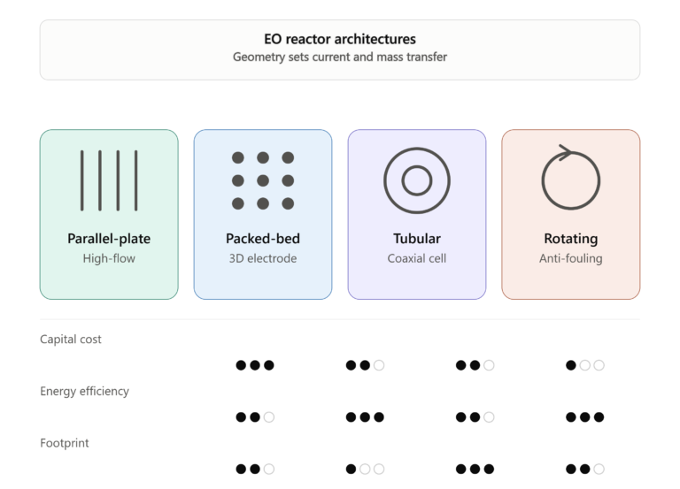
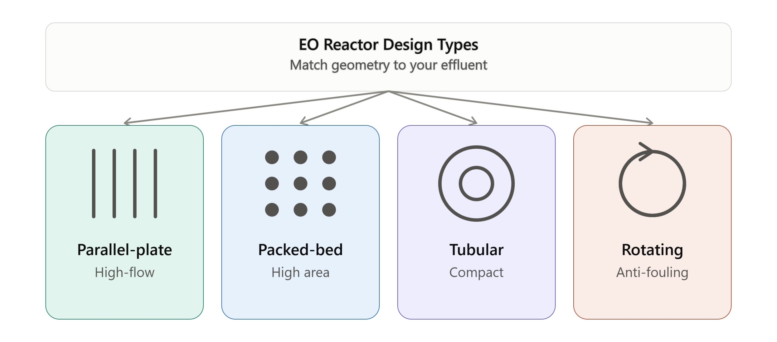
Four architectures cover nearly every industrial EO installation: parallel-plate stacks, packed-bed (3D) electrodes, tubular/coaxial cells, and rotating electrode systems. Each trades off differently between capital cost, footprint, and energy efficiency, and the effluent characteristics usually make the choice for you before cost does.
Four Types of EO Reactor Design Ideas Explained

Parallel-Plate Stacks: Monopolar vs Bipolar
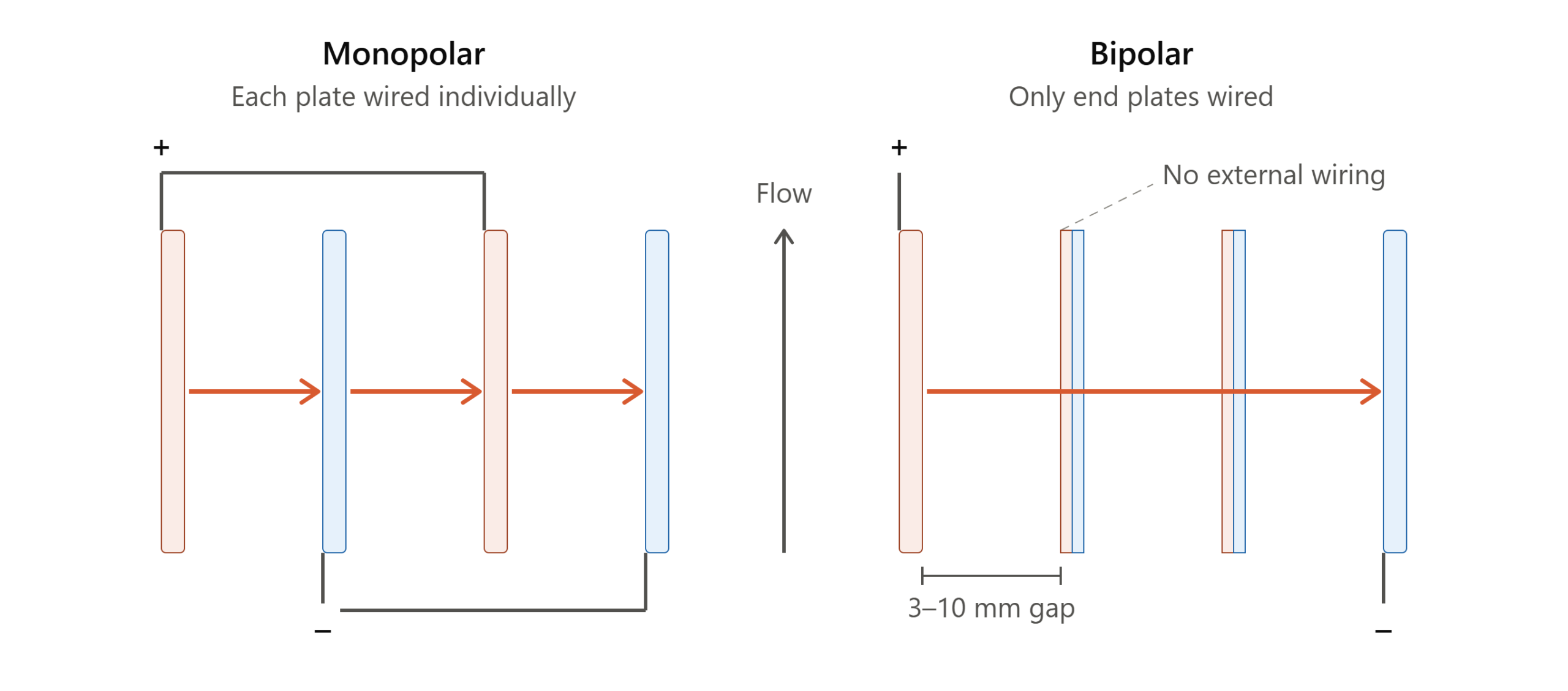
Parallel-plate is the default starting point for most EO skids. Flat electrodes are stacked with narrow gaps (typically 3-10 mm) and wastewater flows between them, either through drilled ports (flow-through) or across the plate face (flow-by).
Monopolar wiring connects every anode and cathode directly to the rectifier bus bars, which keeps individual cell voltage low but drives current draw up. Bipolar wiring only connects the end plates externally; the interior plates carry positive charge on one face and negative on the other, so voltage stacks additively across the pack while current stays low. For a plant sized above a few hundred amps, bipolar wiring is almost always the cheaper power-supply choice, at the cost of a small leakage current loss around plate edges.
EO Reactor Design 101: Monopolar vs Bipolar
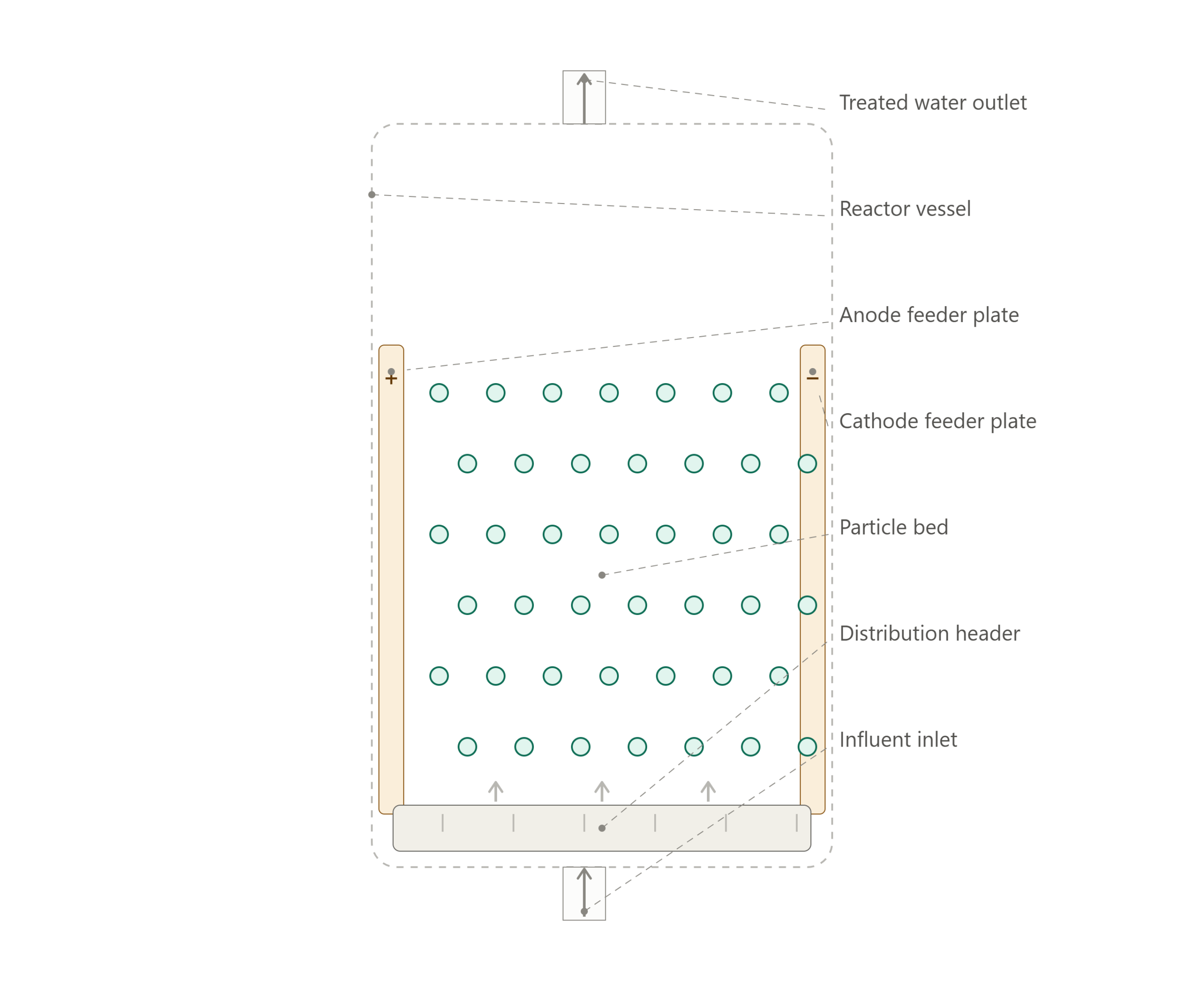
EO Reactor Design 101: Packed-bed EO reactor

Packed-Bed and 3D Particulate Electrodes

Packed-bed reactors fill the interelectrode space with conductive particles (graphite granules, activated carbon, or coated titanium chips) that act as bipolar micro-electrodes. The particle bed multiplies effective surface area per reactor volume by an order of magnitude or more compared to flat plates.

The tradeoff is hydraulics. Bed compaction, channeling, and pressure drop grow with run time as biofilm or scale accumulates in the void spaces. These reactors work best on dilute streams with low suspended solids where the surface-area advantage matters more than the fouling risk, and they need a defined backwash or bed-replacement procedure from day one.

Tubular and Coaxial Cells

Tubular (concentric cylinder) reactors run a rod or tube anode inside a cylindrical cathode shell, or vice versa, with wastewater pumped through the annular gap. The geometry naturally promotes turbulent, well-mixed flow along the electrode surface, which helps keep the process charge-transfer limited rather than mass-transfer limited.

This configuration is common where BDD (boron-doped diamond) electrodes are used, since BDD is typically manufactured as coated tubes or rods rather than large flat sheets. Coaxial cells also simplify sealing compared to a multi-plate stack, which matters for high-pressure or fully enclosed skid designs.                                                                                                                                                          *BDD rod or tube electrode , coating are under research and testing with Evoaeo engineering team as we speak, in this case, use BDD anode plate or mesh if you are trying to build an electrochemical reactor soon.
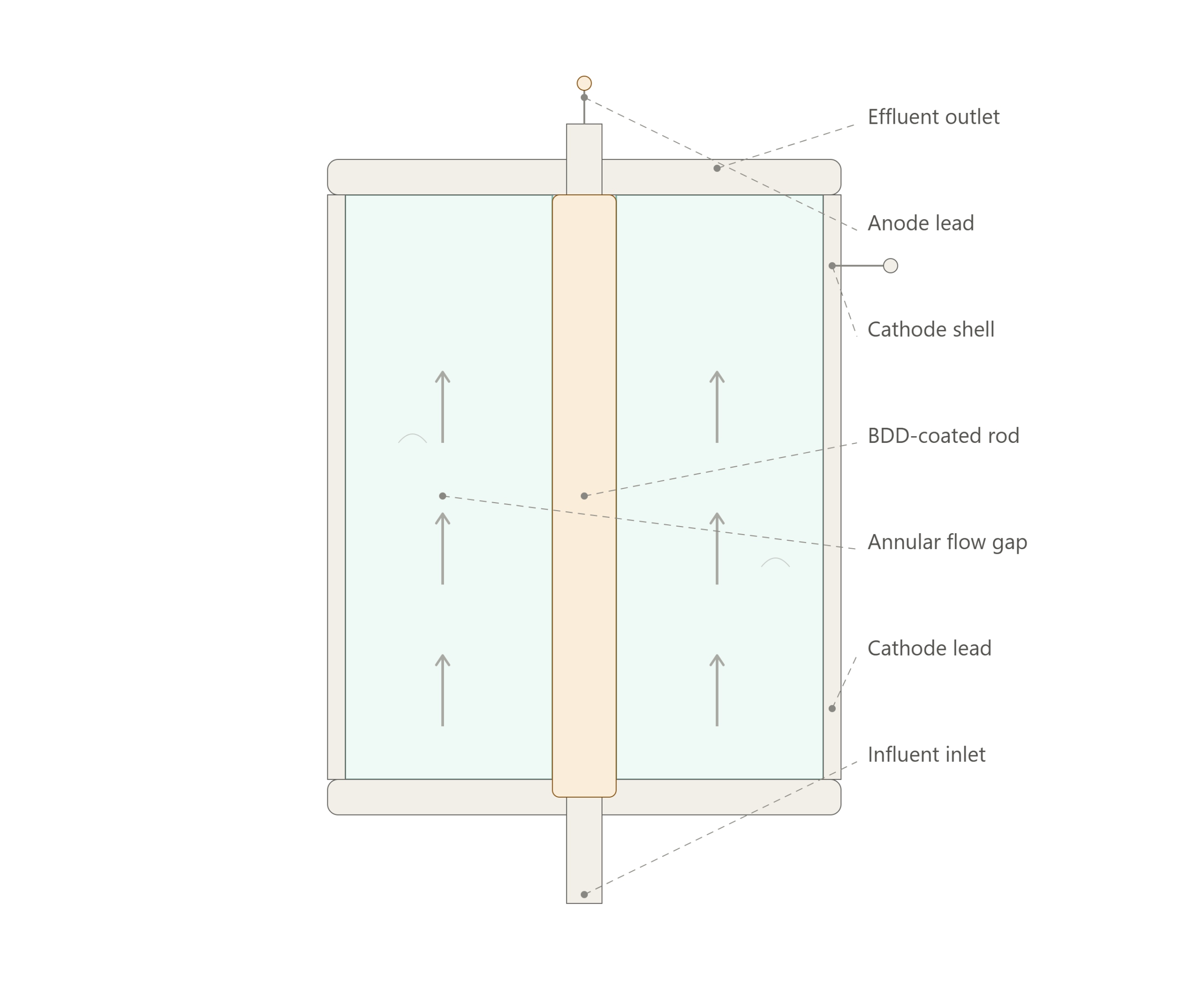
coaxial bdd tube eo reactor electrochemical reactor
EO Reactor Design 101: Coaxial BDD Tube EO reactor
EO Reactor Design 101: Rotating Electrode Systems

Rotating Electrode Systems

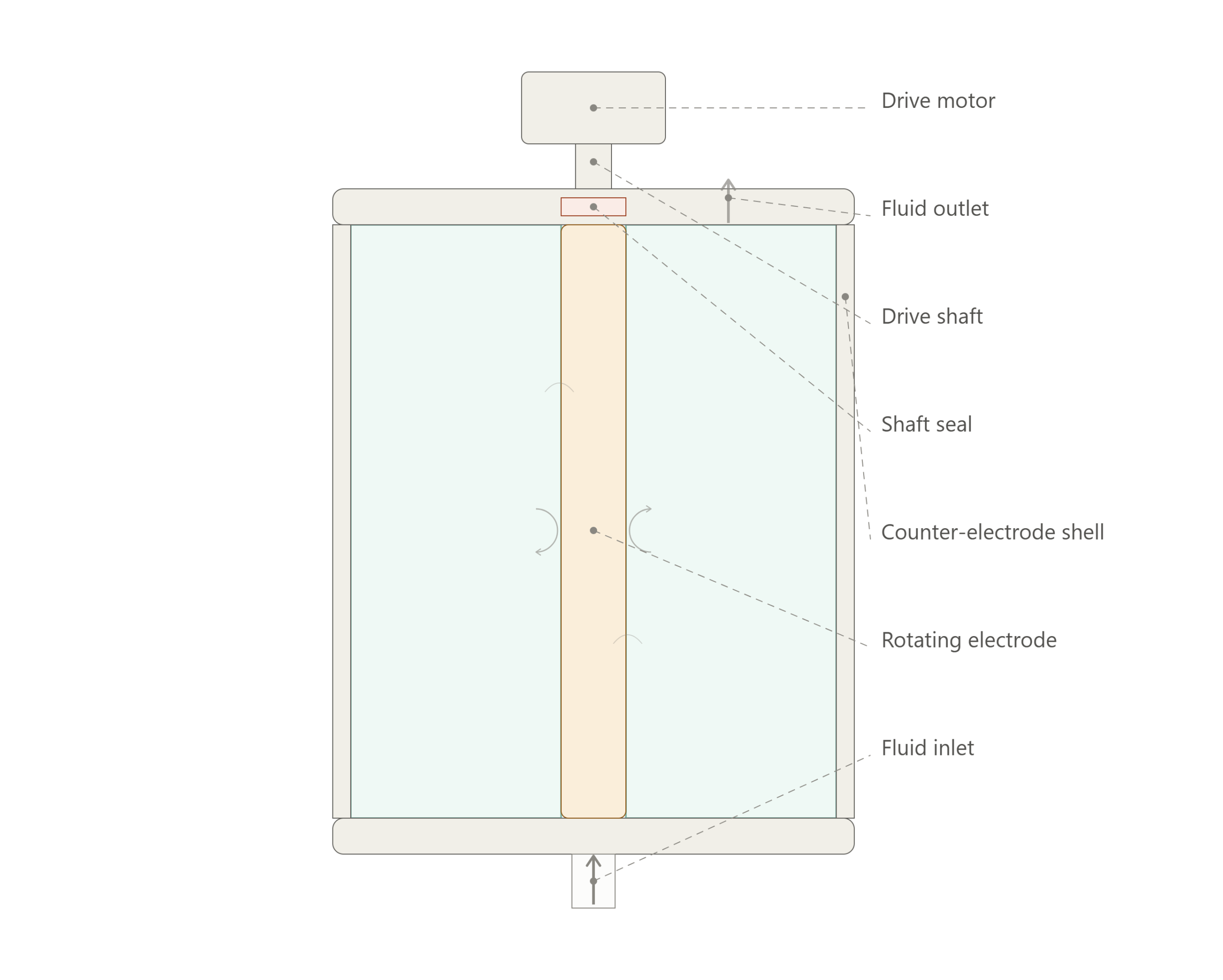
Rotating disc or cylinder electrodes spin the electrode surface through the bulk fluid instead of relying on pump-driven flow to renew the boundary layer. This decouples mass transfer from hydraulic residence time, which is useful for viscous or high-solids streams where pumping alone cannot generate enough shear at the electrode face.

Mechanical complexity is the cost. Rotating seals, bearings, and drive motors add maintenance points that a static plate stack does not have, so this design shows up more often in specialty or low-flow applications than in high-throughput industrial trains.

Key Parameters
01

Typical Plate Gap

3-10 mm for parallel-plate; tighter gaps cut ohmic loss but raise fouling risk
02

Bipolar Voltage Stacking

Cell voltage adds across each interior plate; total stack voltage scales with plate count
03

Flow Regime Target

Turbulent flow (Re > ~4,000) keeps operation charge-transfer limited, not mass-transfer limited

Confirm the fit before you finalize a design

→

Feasibility Assessment Tool

Apply your matrix and stream data to see which reactor class is actually a fit.
→

Engineering Process

See the full bench-to-commercial sequence this reactor decision feeds into.
→

Pilot Test Requirements

What a pilot needs to validate the reactor geometry you are leaning toward.

Reactor Type at a Glance

Common Selection Mistakes

Bench-scale gaps are often tighter than what a full plate stack can hold flat over years of thermal cycling. Verify mechanical tolerance before locking in a gap dimension that assumes lab-level ohmic resistance.
Monopolar wiring is simple to troubleshoot but gets expensive fast in rectifier and busbar cost as current climbs. Model the bipolar alternative before finalizing the power supply spec.
Packed-bed and rotating designs behave very differently under high TSS. A reactor selected on chemistry alone, without a solids profile, is a common source of early fouling complaints.
Fresh reactors rarely show the pressure drop they will carry after months of scale or biofilm buildup. Design the pump and piping for end-of-run conditions, not day-one conditions.

Where does this take you next?

Reactor geometry is usually the first design decision. Where you go next depends on how settled that decision is.

Geometry is settled

You know your reactor class. Move on to sizing it for your actual throughput.

Still comparing options

Run your stream through the feasibility tool to narrow the reactor class before committing.

Not sure EO is the fit

Step back to the decision layer before investing more time in reactor-level detail.

Talk to our process engineers about your application

Send us your flow rate, COD/TOC targets, and solids profile and we will help you match reactor geometry to the effluent, not the other way around.
Decision Gate
Not sure if EO applies? Start with the decision gate before committing to a design path.
Reviewed for technical accuracy by [Reviewer Name, PE — Process / Electrochemical Engineering]. Last reviewed August 2026. Figures and ranges on this page are engineering starting points — verify against your own pilot or vendor data before finalizing a design.

Electrochemical Oxidation Wastewater Treatment — Engineering & System Design — EO Reactor Design Types, How to choose the right configuration to maximum your treatment efficiency.

Scroll to Top