Engineering Services / Conceptual & Process Design
Electro-Oxidation Conceptual & Process Design
Bench data tells you what’s possible. Process design tells you what gets built: the flow diagram, the instrumentation, and the equipment list that a fabrication team and a permitting authority can both work from.
Reviewed for technical accuracy by Janeczka Kowalski, Process / Electrochemical Engineering. Figures and ranges on this page are engineering starting points — verify against your own pilot or vendor data before finalizing a design. The content is created by the Evoaeo engineering team led by Janeczka, All rights reserved.
Process flow diagrams
Mapping the stream from inlet to discharge
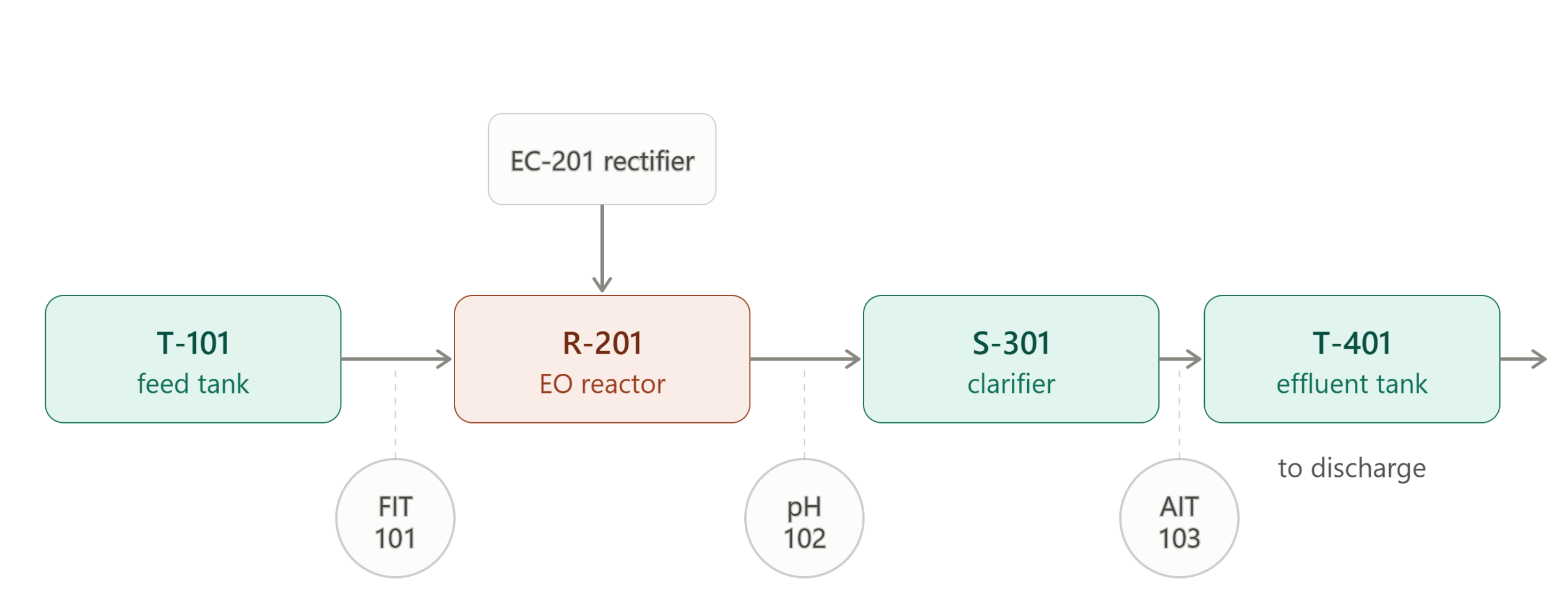
A PFD for an EO system lays out every unit operation in sequence — pretreatment (screening, pH adjustment, oil-water separation where needed), the EO reactor stage itself, any post-treatment such as neutralization or dechlorination, and the monitoring points that confirm the system is meeting its target at each stage. We build this from the treatability study’s recommended treatment train, not from a generic template, since pretreatment needs vary enormously between a clean rinse stream and a high-solids process effluent.
Engineering note
The most common gap we catch at this stage is a stream that needs cooling before it reaches the electrode. Elevated feed temperature from an upstream heat exchanger is easy to miss in a characterization report if temperature wasn’t logged across the full production cycle, and it changes the reactor’s material selection.
P&IDs
Instrumentation, control loops, and safety interlocks
The piping and instrumentation diagram follows ISA-5.1 symbol and tagging convention — every sensor, valve, and control loop gets a standard instrument tag (FIC, AIT, and similar designations) so the drawing reads the same way to any process engineer or fabrication shop reviewing it later, not just the team that produced it. Conductivity and pH probes, ORP monitoring where relevant, flow meters, and the interlocks that shut the rectifier down on a low-flow or high-temperature condition are all specified at this stage.
For enclosed installations, the P&ID also documents the ventilation and hydrogen-monitoring instrumentation required for the off-gas generated at the cathode, and flags where electrical area classification applies. This is also where we size the rectifier’s control mode — constant current versus constant voltage — against the process behavior established in bench testing, since a stream with variable conductivity often needs a different control strategy than one that runs at a steady baseline.
Redundancy philosophy
Where single points of failure are and aren't acceptable
Not every component gets duplicated — redundancy is applied where a single failure would either stop compliance or cause an unsafe condition, not applied uniformly across the whole system regardless of consequence. Feed pumps typically get N+1 sparing on continuous-duty systems, since a pump failure otherwise means an unplanned shutdown; a single rectifier is usually acceptable on smaller systems where downtime has a defined recovery path, but multi-reactor commercial systems often split rectifier capacity across more than one unit so a single rectifier fault doesn’t take the whole train offline.
A short worked example: a continuous-duty pharmaceutical intermediate plant’s design review flagged that a single feed pump, sized for 100% of design flow with no spare, would force a full production stoppage on any pump failure or scheduled maintenance — the process design was revised to two 100%-duty pumps in a lead/standby configuration, adding modest capital cost against a production line where an unplanned stoppage carried a cost many times that difference.
Equipment specification
What ships to fabrication
The output of this phase is a specification package: reactor sizing, electrode material and count, rectifier rating, pump and piping specifications with wetted-material callouts matched to the effluent chemistry, and an instrumentation list with tag numbers that carry through to the automation build. This package is what Reactor Engineering & Electrode Design and System Integration & Automation both work from next.
- Process flow diagram with every unit operation and monitoring point
- P&ID built to ISA-5.1 tagging convention, with control loops and safety interlocks
- Reactor and rectifier sizing basis, traceable to the treatability study
- Materials of construction list matched to matrix chemistry
- Redundancy decisions documented with the consequence-of-failure rationale behind each
- Electrical area classification notes where hydrogen off-gas requires them
Questions About Conceptual & Process Design?
Ready to move from bench data to a buildable design? Looking for process design now? Fill the blanks below to get a process design now.