Engineering Services / Feasibility & Design / Reactor Engineering & Electrode Design
Electrochemical Reactor Engineering & Electrode Design
Electrocehmical reactor geometry, flow behavior, substrate selection, and coating chemistry together determine whether a system reaches its theoretical oxidation potential or leaves performance on the table. This page covers how we design that core.
Reviewed for technical accuracy by Janeczka Kowalski, Process / Electrochemical Engineering. Figures and ranges on this page are engineering starting points — verify against your own pilot or vendor data before finalizing a design. The content is created by the Evoaeo engineering team lead by Janeczka, All rights reserved.
Custom Reactor Geometry Design
Choosing the physical cell configuration
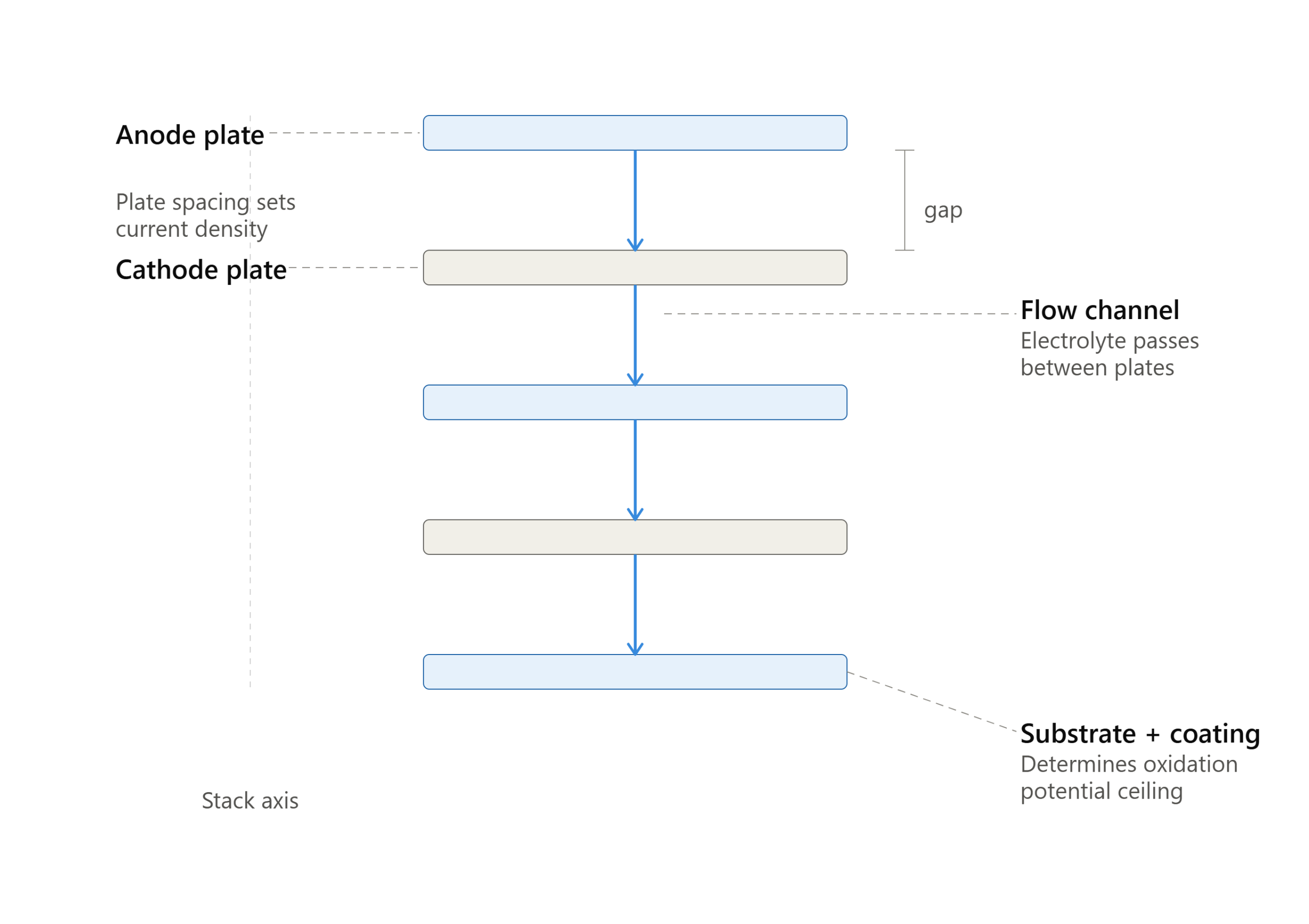
Every stream has a different relationship between flow rate, target contaminant concentration, and required contact time — which is why we don’t default to one reactor format. We evaluate 2D plate-and-frame, 3D packed or fluidized electrode beds, and filter-press configurations against your specific matrix, with plate spacing typically set between 3 and 10 mm depending on conductivity and target current density — tighter spacing reduces ohmic resistance and energy cost on lower-conductivity streams, while wider spacing reduces fouling risk on streams carrying suspended solids.
Electrode count and cell arrangement (monopolar versus bipolar configuration) are sized to hit your removal target at the current density your bench data supports, typically in the 10–300 mA/cm² range depending on electrode material — BDD systems commonly run toward the higher end of that range, while MMO systems are more often optimized in the lower-to-mid range where chlorine-mediated chemistry is doing much of the oxidation work.
Hydrodynamic Reactor Design
Modeling flow so no volume goes unused
A reactor with the right electrode count can still underperform if flow distribution inside it is uneven — effluent that channels past the electrode surface without adequate contact time doesn’t get treated, regardless of the current applied. We use computational fluid dynamics modeling, typically a Reynolds-averaged Navier-Stokes (RANS) turbulence approach validated against tracer-study data from comparable geometries, to identify and eliminate these dead zones before fabrication.
A representative CFD workflow runs through three iterations: an initial geometry model to establish baseline flow distribution, a first redesign targeting any identified dead zones or short-circuiting paths, and a final validation pass confirming residence-time distribution falls within the target range across at least 90% of the reactor volume before the design is released to fabrication. This process typically adds one to two weeks to a reactor design timeline on a new geometry, and is skipped only on configurations closely matching a previously validated design.
Electrode Substrate Selection
Matching substrate to matrix and design life
The titanium substrate underneath the active coating has to hold its dimensional and mechanical integrity across thousands of operating hours in your specific matrix chemistry. Grade 1 titanium offers the best corrosion resistance and is the default choice for high-chloride or otherwise aggressive matrices, while Grade 2 offers somewhat higher mechanical strength at a modest reduction in corrosion margin and is suitable for moderate-chloride streams where mechanical robustness during handling and installation is a bigger factor than incremental corrosion life.
Substrate pre-treatment — typically a controlled surface roughening or etching step — affects coating adhesion and is selected based on both substrate grade and the specific coating chemistry going onto it. We select substrate grade and pre-treatment based on your matrix data, not a single default spec.
Catalytic Coating Optimization
Tuning the coating ratio to your target compounds
For MMO electrodes, the ratio of noble-metal oxides in the coating — iridium, ruthenium, tantalum — sets where the electrode’s oxygen evolution potential (OEP) sits, which in turn determines how much of the applied current goes toward generating hydroxyl radicals versus splitting water unproductively. Coating loading typically runs 8–15 g/m² of total metal oxide, with the iridium fraction increased for streams where OEP needs to sit higher to favor hydroxyl radical generation, and the ruthenium fraction increased where chlorine-mediated pathways are the primary intended mechanism.
We customize this ratio to your target contaminant class rather than shipping a generic coating spec, and validate the selected formulation against bench data before it’s carried into a full commercial coating run.
Engineering note
A coating optimized for one contaminant class can underperform on a stream with a meaningfully different chemistry, even at the same conductivity and chloride level — this is why coating selection is tied to the treatability study’s specific compound data, not just the stream’s general matrix parameters.
Questions About Electrode engineering or electrode?
Questions regarding electrochemical reactor or electrode question specific to your stream? Exploring all around the world to get your complex waste stream treated with enhanced efficiency? Unique geometry, reactor design, help to design MMO or BBD anode based electrochemical reactor? All you need to do is fill the blanks below, we will get back to you as soon as we can.